

Next-Generation Network Packet Broker
Packet Slicing, GTP IP Filtering, Timestamping
The Profitap X2-12800G is a Next-Generation Network Packet Broker (NGNPB) with a total throughput of 12.8 Tbps. It offers an extensive set of features, such as packet slicing, GRE de-tunneling, VXLAN de-tunneling, ERSPAN de-tunneling, and timestamping.
X2-12800G NGNPB provides aggregation, replication, powerful filtering and load balancing in very high bandwidth port monitoring and analysis scenarios. The processing of these features is done at wirespeed in the data plane; data does not have to be forwarded to a co-processor, resulting in no added latency. X2-12800G also features non-conflicting rules creation, meaning all rules are active in parallel with each other, which ensures no conflict between new and existing rules can happen and saves time setting up new rules.
Network Packet Brokers optimize the performance of network analysis and security tools by delivering filtered traffic of interest, helping you solve application performance bottlenecks and troubleshoot problems on the network.
Technical Specifications
Network packet broker features
Filtering
XX-Series X2-Series X3-SeriesFiltering ensures only relevant packets are forwarded to monitoring and security tools using rule-defined criteria. This prevents tool overload, reduces bandwidth consumption, and improves overall performance.
How filtering helps
-
Reduce bandwidth flow to monitoring tools:
By filtering out unnecessary traffic, only relevant packets are sent, minimizing the load on monitoring infrastructure -
Filter on subnets or VLAN:
Filters can select traffic based on specific VLANs or subnets, ensuring targeted network monitoring -
Filter on a list of IPs:
Filters can also allow or block traffic based on specific IP addresses, ensuring that only traffic from relevant IP addresses reaches the tools.
Non-conflicting rules
Non-conflicting rule creation in Network Packet Brokers ensures that all rules can be active in parallel without interfering with each other. This eliminates the need to manually resolve conflicts between new and existing rules, making the setup process faster and more efficient.
By ensuring that each rule operates independently and without overlap, administrators can implement new policies or filters quickly, reducing the risk of errors and streamlining network traffic management. This results in improved performance, easier configuration, and enhanced reliability in network monitoring and security operations.
 |
 |
 |
|---|---|---|
| Flexible configuration with non-conflicting forwarding and filtering rules | Flexible configuration with non-conflicting forwarding and filtering rules | Priority-based rule system |
| Number of filters: | ||
| Up to 512 | Up to 6000 |
Up to 18k TCAM
Up to 10M CPU |
| Filtering capabilities: | ||
|
|
|
|
|
|
|
|
|
|
|
|
Slicing
X2-Series X3-SeriesSlicing reduces data volume and optimizes traffic for monitoring tools by only forwarding specific parts of network packets, such as headers, rather than the entire packet.
Why do you need slicing?
Slicing helps reduce the amount of data that monitoring tools need to process by eliminating irrelevant portions of packets, such as payloads or application-level data. This allows monitoring tools to focus on key information (e.g., headers) without being overwhelmed by excess data.
How slicing helps
-
Reducing Data Volume:
By capturing only specific parts of a packet (like headers), slicing reduces the overall size of traffic sent to monitoring tools. This minimizes bandwidth usage and processing overhead. -
Traffic Optimization:
Slicing ensures that only the essential portions of traffic are sent, reducing unnecessary data flow and making the monitoring process more efficient and faster. -
Increased Storage Efficiency:
By retaining only relevant data, truncation reduces the amount of storage needed for packet captures, enabling longer data retention and reducing costs.
How do we slice traffic?
Profitap Network Packet Brokers perform packet slicing through truncation. This involves cutting packets after a specific number of bytes, retaining only the relevant portion, such as headers or metadata.
|
|
|
|---|---|---|
| No slicing support | 64–9215 bytes truncation, line rate | 60-65535 bytes truncation |
| - | From the start of the packet | Packet Header Only Selective Slicing |
| - | - | Dynamic (header-based) slicing: Remove the TCP header only by playing with offset values |
Timestamping
X2-Series X3-SeriesHigh-quality timestamping is critical for effective network monitoring and troubleshooting, particularly in latency-sensitive applications like financial trading systems, fintech services, and Voice over IP (VoIP) communications.
Precise timestamping enables engineers to measure, analyze, and optimize network latency. With accurately timestamped network packets, network engineers can better correlate events and analyze packet flows over time. This enables more efficient network tracing and diagnostics, as the exact sequence and timing of packets are preserved.
Sync with IEEE 1588 (PTP)
Timestamping can be synchronized with Precision Time Protocol (PTP) IEEE 1588 , allowing nanosecond-level precision across devices. This synchronization ensures that timestamps across different devices in the network are perfectly aligned, providing a unified and accurate view of network performance for time-sensitive analysis.
|
|
|
|---|---|---|
| No timestamping support | Timestamping on ingress port | Hardware timestamping (PTPv2 IEEE1588 sync) |
| - | Line rate | Line rate |
| - | PTPv2 (IEEE1588) sync on dataplane | Timestamp is added as a trailer to an ethernet frame |
| - | Timestamp using ERSPAN type 3 standard headers | - |
Aggregation
XX-Series X2-Series X3-SeriesAggregation combines traffic from multiple sources into one stream. This helps simplify the monitoring process, allowing tools to analyze all the data together.
Aggregation is helpful in environments with traffic coming from various sources (e.g., multiple TAP or SPAN links). Merging these streams ensures comprehensive monitoring while reducing the complexity of managing multiple separate data feeds.
How do we Aggregate?
- VLAN tag on ingress: Incoming traffic is labeled with a unique VLAN ID as it enters the NPB. This feature is highly beneficial for network monitoring and analysis because it provides a way to categorize and distinguish traffic based on its source.
- VLAN tag on egress: Traffic is labeled with the VLAN ID as the traffic exits the NPB toward the monitoring device. When multiple streams are aggregated onto a single output port, you can use different VLAN IDs to keep them logically separate. This way, the monitoring device (e.g., a packet capture appliance, SIEM, or analysis tool) knows which packets belong to which source or rule set.
- Rule VLAN tagging: Instead of assigning one VLAN ID to all egress traffic on a port, a specific rule is set up in the NPB. Traffic matching each rule (e.g., by IP address range, protocol, port, etc.) is assigned a unique VLAN ID. With the ability to define many rules, you can handle a large number of network segments or services, such as database traffic or email traffic, each labeled with its own VLAN ID.
|
|
|
|---|---|---|
| Many-to-any | Many-to-any | Many-to-any |
| Ingress VLAN tagging | Egress/rule VLAN tagging | Ingress/egress/rule VLAN tagging |
| Oversubscription counter displaying packets dropped | Oversubscription counter displaying packets dropped | Oversubscription counter displaying packets dropped |
|
Non-blocking:
Oversubscribing one port will not affect the performance of other ports |
Non-blocking:
Oversubscribing one port will not affect the performance of other ports |
Non-blocking:
Oversubscribing one port will not affect the performance of other ports |
Replication
XX-Series X2-Series X3-SeriesReplication is the process of duplicating network traffic and sending identical copies to multiple monitoring or security tools. This allows the same traffic to be analyzed by different systems without affecting the original data flow.
Replication ensures that multiple tools can analyze the same traffic for different purposes, such as performance monitoring, security analysis, data storage, and compliance checks, without interrupting or altering the original traffic. This improves network visibility and ensures comprehensive monitoring across different systems.
How replication helps
- Enables multiple analyses without affecting the original traffic
- Supports security, performance, and compliance monitoring simultaneously
- Increases network visibility by distributing identical traffic to various tools
By replicating traffic, organizations can deploy different monitoring and analysis tools in parallel, ensuring each tool has the data it needs for its specific purpose. This enhances network visibility and troubleshooting capabilities across different departments or functions.
How do we Replicate?
Non-conflicting rule creation ensures that existing rules do not conflict with new rules. This means that traffic is truly replicated for each active rule.
Overlapping/parallel rules
XX-Series and X2-Series network packet brokers run all rules simultaneously. This simplifies
configuration because new rules
will not override existing ones. DROP rules take precedence over ALLOW rules in XX, and with the
X2-Series, you can
configure rule priorities if needed. This parallel approach makes it easy to create scenarios like
forwarding live traffic
and simultaneously sending a copy for analysis without running into rule conflicts.
|
|
|
|---|---|---|
| Any-to-many | Any-to-many | Any-to-many |
| Non-conflicting rule creation | Non-conflicting rule creation | Priority based rule creation |
| - | - | Conflicting rule |
Tunnel creation/termination
X2-Series X3-SeriesTunneling is the process of encapsulating one type of network traffic within another protocol to securely transmit it across different networks. It allows traffic to be transferred through networks that may not support the original protocol or require secure transportation.
Tunneling is often used in virtual private networks (VPNs). It can also set up efficient and secure connections between networks, enable the usage of unsupported network protocols, and, in some cases, allow users to bypass firewalls.
Tunnel Termination refers to the end of this encapsulated path, where the data is extracted and forwarded to its intended destination.
Why is Tunneling important?
Tunneling is essential for securely transmitting data across networks, particularly when data must pass through untrusted or incompatible environments. It ensures that the original traffic remains protected and can traverse various networks without being exposed to external threats.
How Tunneling helps:
-
Secure transmission:
Tunneling adds an extra layer of security by encapsulating traffic, protecting data from interception or tampering as it crosses untrusted networks. -
Protocol compatibility:
Tunneling enables different network protocols to communicate over incompatible networks. For example, IPv6 traffic can be tunneled through an IPv4 network. -
Remote access:
Tunneling is widely used in Virtual Private Networks (VPNs) to allow remote users to securely access corporate networks as if they were locally connected. -
Flexible Transmission:
Supports seamless communication across different types of networks, enhancing network interoperability and security.
Tunnel Termination:
-
Decapsulation:
At the endpoint, the tunnel is terminated, and the encapsulated data is decapsulated, removing the tunnel’s outer layers and forwarding the original packet to its final destination. -
Controlled Access:
Ensures that only authorized devices can access the tunnel termination points, preventing data interception or unauthorized access.
Tunneling examples
Tunneling traffic directly to a probe
The NPB acts as the tunnel endpoint, decapsulating the traffic, such as VXLAN or GRE, and
distributing it to a connected
probe. This offloads decapsulation from the probes, allowing them to focus on more critical analysis
tasks and conserve
processing resources.
Tunnel termination on NPB
Traffic tunneling to another NPB for termination on the NPB is common in virtual-to-physical
environments. Encapsulated
traffic from virtualized servers is routed to a physical NPB, which terminates the tunnel and
decapsulates the traffic,
enabling centralized management of tunnel termination.
|
|
|
|---|---|---|
| - |
Tunnel Creation:
ERSPAN (type 2 and 3), GRE-TAP |
Tunnel Creation:
CPU: ERSPAN (type 2 and 3) VXLAN ASICS: GRE-TAP, IP GRE, |
| - |
Tunnel Termination:
ERSPAN (type 2 and 3), GRE-TAP, VXLAN |
Tunnel Termination:
CPU: ERSPAN (type 2 and 3), GRE-TAP, IP GRE, VXLAN, CFP, GTP |
| - |
Tunnel Stripping (ingress):
ERSPAN (type 2 and 3), GRE-TAP, VXLAN |
Tunnel Stripping (ingress):
ASICS: ERSPAN (type 2 and 3), GRE-TAP, VXLAN, CFP, GTP |
| - |
Tunnel Stripping (egress):
ERSPAN (type 2 and 3), GRE-TAP, VXLAN, IP in IP, Teredo |
Tunnel Stripping (egress):
CPU: VXLAN, GRE-TAP, IP GRE, DCE |
Load balancing
XX-Series X2-Series X3-SeriesLoad Balancing is the distribution of network traffic across multiple monitoring or security tools to ensure efficient data processing and prevent overload. Typically, this is done on Layer 3 or Layer 4 of the OSI model.
L3 Load Balancing (Layer 3)
Layer 3 load balancing distributes traffic based on IP addresses (source or destination). It directs
packets to different
tools or devices depending on IP hash values.
L4 Load Balancing (Layer 4)
Layer 4 load balancing also uses port numbers (TCP/UDP), in addition to IP addresses, to distribute
traffic more granularly.
This allows better distribution when multiple sessions or services use the same IP address.
Load balancing relies on hashing techniques to determine how traffic is split. The system computes a hash value based on IP addresses (L3) or port numbers (L4), which it uses to distribute traffic consistently across different monitoring tools or devices. Grouping tools together ensures the load is evenly spread, preventing any tool from becoming overwhelmed.
Why do we have L3 and L4 options?
-
L3 Load Balancing is sufficient when traffic flows from various IP addresses, but it can be limited when IPs are fewer or when only specific flows need balancing.
For example, with a TAP placed between a router and a firewall, only two IP addresses (router and firewall) are visible. As a result, L3 load balancing will not work effectively because there is no variation in IP addresses to distribute traffic. If this is the case, Layer 4 load balancing is a better option.
- L4 Load Balancing offers finer control by considering not just IPs but also TCP/UDP port numbers to make more granular traffic distribution decisions. For example, it allows traffic to be divided by application (e.g., web, email) based on port numbers. This is useful when the same IP addresses handle multiple services or sessions.
Key Benefits
-
Port-Based Load Balancing:
With L4 load balancing, port numbers are used to distribute traffic more effectively when IP-based balancing is not sufficient, such as between routers and firewalls with only two IPs. -
Optimized Resource Usage:
Ensures tools are not overloaded and resources are used efficiently. -
Increased Redundancy and Reliability:
This prevents system failures by distributing traffic evenly and rerouting traffic in case of tool or network failures. -
Improved Monitoring Efficiency:
Multiple monitoring tools can handle traffic in parallel, improving analysis and detection capabilities.
Round Robin
In Round-Robin mode, traffic is distributed equally across all output ports. This mode is typically
used when creating an
uplink to move traffic between appliances.
Flow Hash
In Flow Hash mode, traffic is distributed based on the selected header fields. This mode is
suggested when multiple tools
are attached and ensures that each one gets consistent traffic to perform flow detection and
monitoring. Note that if Flow
Hash is used with source AND destination options enabled for L3 or L4, the unit will distribute the
traffic, maintaining
flow symmetry and consistency.
|
|
|
|---|---|---|
| Flow Hash (L3, L4) | Flow Hash (L3, L4, IP and Source/destination) | Flow Hash (L3, L4) |
| - | Round Robin | Round Robin |
High Availability (HA)
XX-Series X2-Series X3-SeriesHigh Availability (HA) is a system design approach that ensures continuous operational performance by minimizing downtime. In networking, HA ensures that monitoring, security, or operational tools remain operational even during hardware failures or maintenance.
How do we support HA?
Profitap packet brokers support High Availability (HA) deployments by ensuring resilient traffic distribution even when links fail. The XX, X2, and X3 models support dynamic Link Aggregation (LAG), which automatically redistributes traffic to remaining links if one goes down, minimizing data loss and downtime. Additionally, the X3 offers both dynamic and static LAG modes, as well as enhanced port redundancy features for an extra layer of protection. This robust design helps to keep monitoring and security probes continuously fed with critical data, sustaining seamless oversight and protection in any HA environment.
When configured in High Availability (HA), the XX and X2-Series network packet brokers forward mirrored traffic to multiple probes using load balancing to distribute incoming traffic between both probes simultaneously for optimal performance. The NPB monitors the status of each probe in its load balance group. If one probe experiences a failure and its port link goes down, the NPB reconfigures the load balance group so that all traffic is directed to the remaining active probe. By automatically adapting to probe availability, the NPB provides robust and continuous network visibility.
|
|
|
|---|---|---|
| Active-Active dynamic load balancing | Active-Active dynamic load balancing | Port Redundancy |
| - | - | Load Balance group redundancy |
| - | - | Load Balance Port Replacement (Cascade Group) |
Web GUI Overview
X2-Series integrates a web-based management interface that allows users to configure and monitor the behavior of the device. Running locally on the device and designed with user experience and ease of use in mind, this interface enables advanced configuration settings to be set and applied quickly and easily.
This web-based interface allows easy access from any OS or platform.
Device Status
Device status offers a quick overview of operational statistics related to the packet broker hardware. Measured temperatures are recorded with a history of 72 hours, to allow filtering back in time on temperature statistics.
Port Management
Port management offers an instant overview of port status and speed. Users control the configuration of all QSFP modules, where each module offers additional information in the specific status section.
Port Statistics
Port statistics displays and monitors the statistics counter for each of the device interfaces. Users can view or export this information for a later analysis. It is also possible to easily compare the traffic bandwidth on each port.
Traffic Management
Define how the traffic will flow through the device interfaces. Using a direct control interface, users are able to define aggregation, duplication, and filtering rules. Advanced actions can be defined to manipulate the traffic, adding label information, or stripping undesired headers.
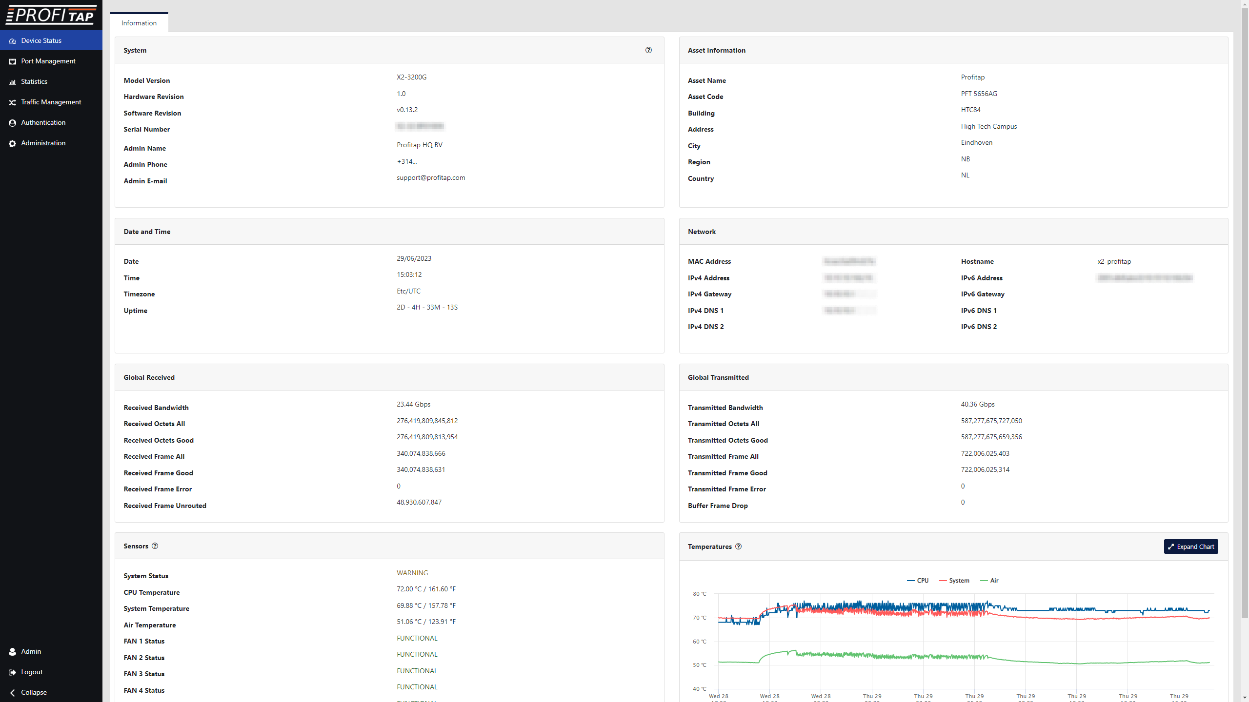
Device Status
Device status offers a quick overview of operational statistics related to the packet broker hardware. Measured temperatures are recorded with a history of 72 hours, to allow filtering back in time on temperature statistics.

Port Management
Port management offers an instant overview of port status and speed. Users control the configuration of all QSFP modules, where each module offers additional information in the specific status section.

Port Statistics
Port statistics displays and monitors the statistics counter for each of the device interfaces. Users can view or export this information for a later analysis. It is also possible to easily compare the traffic bandwidth on each port.
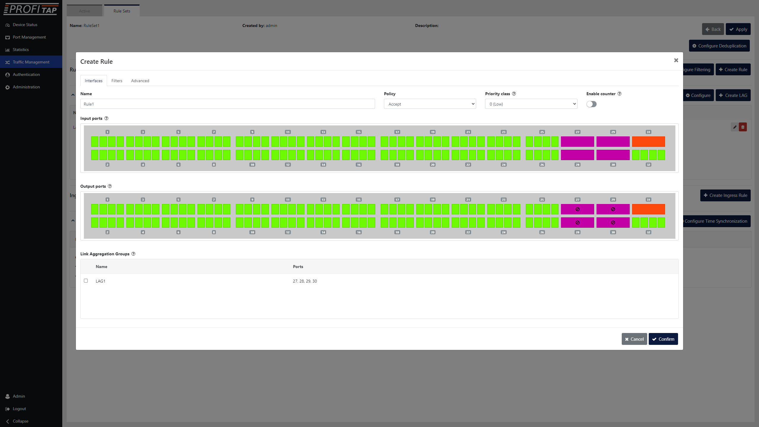
Traffic Management
Define how the traffic will flow through the device interfaces. Using a direct control interface, users are able to define aggregation, duplication, and filtering rules. Advanced actions can be defined to manipulate the traffic, adding label information, or stripping undesired headers.
-
- Aggregation, replication, filtering, VLAN tagging and stripping, MPLS stripping and load balancing (any-to-any, any-to-many, many-to-many)
- Packet slicing, timestamping, GTP IP filtering, GRE de-tunneling, VXLAN de-tunneling, and ERSPAN de-tunneling
- Local and remote management (CLI, GUI, SNMP, Syslog)
- Layer 2–4 filtering
- RESTful API support
- Flexible role-based management access
- In-line mode and in-line tool sharing
- TACACS+/RADIUS/LDAP authentication
- Redundant, hot-swappable PSUs and fan modules
- Supports 10GbE, 25GbE, 40GbE, 50GbE, 100GbE, 200GbE, 400GbE
- Full control over high speed network traffic for monitoring thanks to its intuitive GUI.
- Multiple filter rules per port in any combination for various routing, filtering, duplication or replication and many more options can be configured by an innovative GUI to allow instant adaptation to all kinds of analysis.
- An integrated archive gives quick access to establish filter scenarios on the fly or allow instant changes to ease meeting the current requirements.
-40V–-60 VDC
| PT-1G-BT-45 | PT-1G-SX-85 | PT-1G-LX-31 | PT-10G-BT-45 | PT-10G-SR-85 | PT-10G-LR-31 |
|---|---|---|---|---|---|
 |
 |
 |
 |
 |
 |
| 1000BASE-T SFP 100m (RJ45) | 1000BASE-SX SFP 850NM 550M (LC) | 1000BASE-LX/LH SFP 1310nm 20km (LC) | 10GBASE-T SFP+ 30M (RJ-45) | 10GBASE-SR SFP+ 850NM 300M (LC) | 10GBASE-LR SFP+ 1310NM 10KM (LC) |
| PT-25G-SR-85 | PT-40G-SR4-85 | PT-40G-LR4-31 | PT-40G-PLR4-31 | PT-40G-SR-BD | PT-40G-SR-BD-RX |
|---|---|---|---|---|---|
 |
 |
 |
 |
 |
 |
| 25G SFP28 850nm 100m (LC) | 40GBASE-SR4 QSFP+ 850NM 150M (MTP/MPO) | 40GBASE-LR4 QSFP+ 1310NM 10KM (LC) | 40GBASE-PLR4 QSFP+ 1310nm 10km (MTP/MPO) | 40GBASE-SR-BiDi QSFP+ 150m (LC) | 40GBASE-SR-BiDi QSFP+ 150m (LC) Rx only |
| PT-100G-SR4-85 | PT-100G-LR4-31 | PT-100G-SR-BD-RX | PT-400G-SR8-85 | ||
|---|---|---|---|---|---|
 |
 |
 |
 |
||
| 100GBASE-SR4 QSFP28 850nm 100m (MTP/MPO) | 100GBASE-LR4 QSFP28 1310nm 10km (LC) | 100GBASE-SR-BiDi QSFP28 100m (LC) Rx only | 400GBASE-SR8 QSFP-DD 850nm 100m (MTP/MPO) |


